- Pronouns
- he/him
- TNP Nation
- El_Fiji_Grande
Introduction
This guide will teach you how to solve problems in which forces are applied to a simple structure, such as a truss, or cantilever beam. These problems assume that the structure is static (not in motion), which is typically what you want if, for example, the object is a building, or a bookshelf, or a balcony. You wouldn't want these objects to fail, so we assume that they are static. This will allow us to solve for the internal forces in the structure, which we can then use to determine the type of material we will use to construct it such that these requirements are met.
The first step in analyzing a structure is to draw it. I tend to make this initial drawing much like a Free Body Diagram (FBD) but still include the supports. A good idea is to use grid paper - or better yet, engineering paper - for these drawings. This will help you draw the system neatly. Use of a ruler and protractor can also help. Mark the supports with the corresponding symbol.
Types of Connections

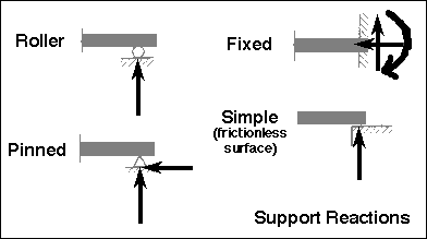
There are four main types of connection. A roller is denoted by a circle, or by a triangle supported by two circles. A pin connection is denoted by a triangle upon which the object rests. A fixed connection is inset into the supporting surface. A simple support is merely resting on the surface: hash marks are drawn where it contacts the surface. When drawing the Free Body Diagram (FBD), note the arrows for each connection. These show the supporting reactions, and include reactions in the x, y, and z directions, as well as moments about the x, y, and z axes.
Solving for Reactions
Once your FBD is complete, you can start solving for the reactions. It is helpful to label the intersections and points of interest on the structure with letters, assigned in a logical manner. Reactions should also be labeled. Say you have reactions in the x and y directions at point A. These would be labeled Ax and Ay.
As stated above, we will assume that the structure is static. Not only is it not moving, but it has no acceleration. This allows us to simplify Newton's Second Law of Motion. It originally states that F=ma, where F is force, m is mass, and a is acceleration. Since we know that the acceleration is zero because the structure is static, we know that F = 0 irrespective of mass. Or, more correctly, the sum of the forces equals zero, as denoted by ?F = 0, in each direction. Additionally, the sum of the moments equals zero, as denoted by ?M = 0. A moment is defined as the product of a force and the distance that force is applied away from a reference point. A special kind of moment is a torque, which is applied around the longest axis of an object.
This results in four main equations:
?Fx = 0
?Fy = 0
?Fz = 0
?MReference Point = 0
Solving for the reactions is now a simple process of summing all of the forces and reactions in each direction, as well as summing the moments about a critical point. A good trick is to try to get forces to cancel. If a reaction points in a given direction and no force opposes it, then that reaction must be equal to zero for the assumption of statics to hold. If a force or reaction is directed through a point, try summing moments about that point, as those forces and reactions will cancel. You will often be left with a system of equations, which, so long as you have as many variables as you have independent equations, is trivial to solve. It takes practice to recognize tricks to solve each problem more quickly.
Two Force Members
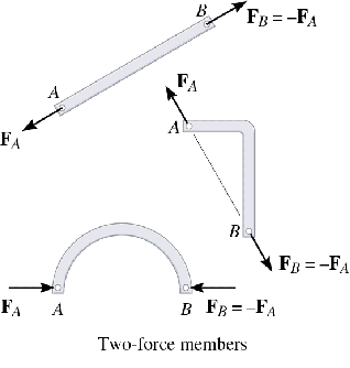
Two force members are parts of a structure that are only subjected to forces at two points, typically at each end of the member. In a two force member, the lines of action of the resultants of the forces acting at each of the two points are equal and opposite and pass through both points. That's a mouthful! To help clarify, shown below are examples of two force members.

Solving for Internal Forces
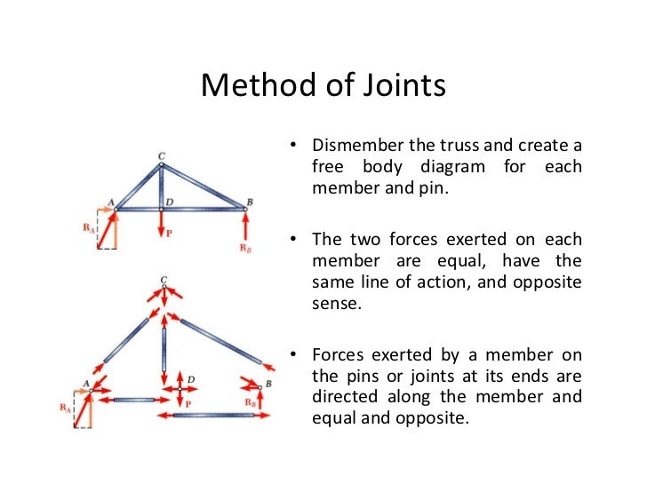
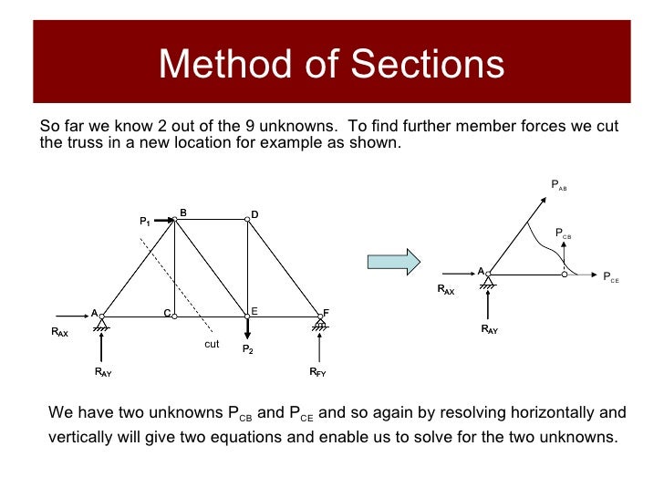
There are two primary methods for solving for internal forces within members: the method of joints and the method of sections. Both are inherently quite similar.
Method of Joints:
 Method of Sections:
 In my experience, solving for internal forces of beams and rods can take a staggeringly long time. Most professors will assign simple problems for homework and on exams that only require you to know the method of solving in principle, and these problems can still take five minutes each. However, the real world involves much more complicated and tedious problems, which can take more time to solve than you might expect, if solving by hand. Imagine the monumental effort it would take to solve for the internal forces of a large truss structure, such as a bridge, with hundreds if not thousands of elements!
This guide will teach you how to solve problems in which forces are applied to a simple structure, such as a truss, or cantilever beam. These problems assume that the structure is static (not in motion), which is typically what you want if, for example, the object is a building, or a bookshelf, or a balcony. You wouldn't want these objects to fail, so we assume that they are static. This will allow us to solve for the internal forces in the structure, which we can then use to determine the type of material we will use to construct it such that these requirements are met.
The first step in analyzing a structure is to draw it. I tend to make this initial drawing much like a Free Body Diagram (FBD) but still include the supports. A good idea is to use grid paper - or better yet, engineering paper - for these drawings. This will help you draw the system neatly. Use of a ruler and protractor can also help. Mark the supports with the corresponding symbol.
Types of Connections

There are four main types of connection. A roller is denoted by a circle, or by a triangle supported by two circles. A pin connection is denoted by a triangle upon which the object rests. A fixed connection is inset into the supporting surface. A simple support is merely resting on the surface: hash marks are drawn where it contacts the surface. When drawing the Free Body Diagram (FBD), note the arrows for each connection. These show the supporting reactions, and include reactions in the x, y, and z directions, as well as moments about the x, y, and z axes.
Solving for Reactions
Once your FBD is complete, you can start solving for the reactions. It is helpful to label the intersections and points of interest on the structure with letters, assigned in a logical manner. Reactions should also be labeled. Say you have reactions in the x and y directions at point A. These would be labeled Ax and Ay.
As stated above, we will assume that the structure is static. Not only is it not moving, but it has no acceleration. This allows us to simplify Newton's Second Law of Motion. It originally states that F=ma, where F is force, m is mass, and a is acceleration. Since we know that the acceleration is zero because the structure is static, we know that F = 0 irrespective of mass. Or, more correctly, the sum of the forces equals zero, as denoted by ?F = 0, in each direction. Additionally, the sum of the moments equals zero, as denoted by ?M = 0. A moment is defined as the product of a force and the distance that force is applied away from a reference point. A special kind of moment is a torque, which is applied around the longest axis of an object.
This results in four main equations:
?Fx = 0
?Fy = 0
?Fz = 0
?MReference Point = 0
Solving for the reactions is now a simple process of summing all of the forces and reactions in each direction, as well as summing the moments about a critical point. A good trick is to try to get forces to cancel. If a reaction points in a given direction and no force opposes it, then that reaction must be equal to zero for the assumption of statics to hold. If a force or reaction is directed through a point, try summing moments about that point, as those forces and reactions will cancel. You will often be left with a system of equations, which, so long as you have as many variables as you have independent equations, is trivial to solve. It takes practice to recognize tricks to solve each problem more quickly.
Two Force Members
Two force members are parts of a structure that are only subjected to forces at two points, typically at each end of the member. In a two force member, the lines of action of the resultants of the forces acting at each of the two points are equal and opposite and pass through both points. That's a mouthful! To help clarify, shown below are examples of two force members.

Solving for Internal Forces
There are two primary methods for solving for internal forces within members: the method of joints and the method of sections. Both are inherently quite similar.
Method of Joints:


